


Features
SeedStar™ XP monitoring system
SeedStar XP overview
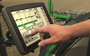 SeedStar XP shown on the GreenStar™ 3 2630 Display
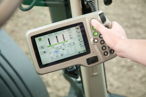 SeedStar XP shown on the GreenStar 2 1800 Display
Building upon the foundation of SeedStar 2, the SeedStar XP system takes planter monitoring to the next level. SeedStar XP is compatible with the GreenStar 2 1800 and 2600 Displays, GreenStar 3 2630 Display, the Gen 4 4200 CommandCenter™ Display, the Gen 4 4600 CommandCenter Display, the 4240 Universal Display, and the 4640 Universal Display. SeedStar XP is not compatible with the Gen 4 Extended Monitor.
Specific information about how the planter is performing enables the operator to make needed adjustments for implement optimization.
The SeedStar XP planting functions are fully integrated with the full spectrum of Precision Ag Technology applications such as Swath Control Pro™ system for planters, Section Control, GreenStar AutoTrac™ assisted steering system, John Deere Operations Center, Documentation, and others. Integrated planting technologies for better asset utilization and ease of use is just part of what SeedStar XP provides.
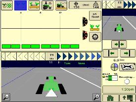
SeedStar XP seed singulation monitoring
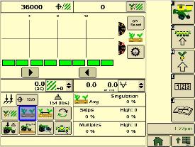 SeedStar XP seed singulation planter run page
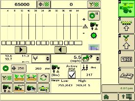
Understanding the meter singulation performance on the planter is critical to minimizing the amount of seed multiples and skips. As a result, the SeedStar XP monitoring system provides real-time information from the row-units about the overall seed singulation performance.
As seen in the screen shot image above, seed multiple information is displayed on the top portion of the planter-at-a-glance bar with seed skip information on the lower portion. This provides the operator a better understanding of relative seed multiple and skip data on a row-unit basis, all within one easy glance.
Also, within the seed singulation planter run page, information about row-units with the highest percentage of seed multiples and skips is provided in order to make necessary adjustments for better planter optimization.
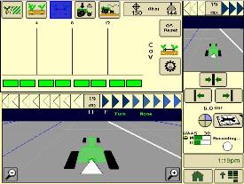
SeedStar XP row-unit ride dynamics planter run page
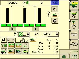 SeedStar XP ride dynamics planter run page
While operating a planter, travel speed and field conditions can affect the amount of row-unit bounce that is experienced. Excessive row-unit bounce or vertical motion can cause problems with meter performance. To better understand the amount of row-unit vertical motion when travelling through a field, the SeedStar XP monitoring system provides real-time information on row-unit ride dynamics.
As seen in the ride dynamics planter-at-a-glance screen shot image above, the SeedStar XP system provides ride dynamic information for each sensor node that is mounted on the planter. Each sensor node transmits ride dynamic information for each planter frame section to allow for the operator to make necessary operating adjustments to improve overall planting performance.
SeedStar XP row-unit downforce planter run page
 SeedStar XP downforce planter run page
As row-unit downforce systems gradually change from heavy-duty downforce springs to pneumatic downforce, being able to understand the amount of as-applied row-unit downforce is needed while operating the planter.
With various soil conditions, moisture, etc. experienced while planting, it is imperative to have the ability to change actual row-unit downforce to have enough force for the Tru-Vee openers to penetrate the soil media. However, in some conditions, having too much downforce applied to the row-units for effective opener penetration could cause problems with side wall compaction from the gauge wheel.
Side wall compaction within the seed furrow can cause hatchet roots to develop, or roots that do not have the ability to penetrate the seed furrow soil media. This could lead to poor plant emergence and eventually lower overall yield performance.
With the SeedStar XP monitoring system, row-unit downforce information is measured by the downforce sensor and sensor nodes and transmitted to display in the tractor cab (as seen in the image above). The row-unit downforce information is displayed on the top portion of the planter-at-a-glance bar with more row-unit downforce information on the lower portion.
Two different control options are available on 1775NT, 1795, and DB Series Planters for pneumatic downforce. The base pneumatic downforce system requires manual control of the downforce to maintain the desired planting results or row-unit margin. Optional active pneumatic downforce takes SeedStar XP even further by removing constant downforce adjustments from the operator and actively controlling the downforce system to maintain a desired target margin.
The 1745 Planter with pneumatic downforce and SeedStar XP will require manual control of the downforce to maintain row-unit margin.
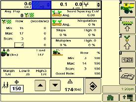
SeedStar XP seed spacing monitoring
 SeedStar XP seed spacing planter run page
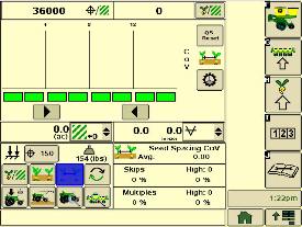
Throughout the planting process, obtaining good seed spacing is critical toward achieving plant growing conditions for maximum yield potential.
Today, many items are adjusted on the planter prior to planting to optimize overall seed spacing performance. After such adjustments are made, information about the actual seed spacing performance during planting was missing within the planter monitoring system. With SeedStar XP, seed spacing information is transmitted live via the GreenStar display to show the operator exactly what is happening with the planter behind them.
The SeedStar XP transmits seed spacing information onto the planter-at-a-glance bar for easy understanding of planter seed spacing performance. Also, information about seed skips and multiples is provided to help understand actual planter meter performance and other related system functions in order to make necessary adjustments if needed.
NOTE: Seed spacing and seed singulation information is only available when planting crops with seed drop rates below 40 seeds per second such as corn. With higher population crops such as soybeans the system does not provide spacing and singulation information because the number of seeds dropping per second is much higher.
Components and operation
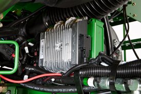 Planter main 2 controller
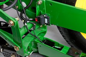 Sensor node assembly installed
The SeedStar XP monitoring system contains the following components in order to support the planting data transfer to the GreenStar 2 Displays:
- Seed monitor/variable-rate (SMVR) controller with model year 2011 or newer software
- Planter main 2 controller (installed on all SeedStar XP eligible models for model year 2011 or newer)
- Sensor node(s)
- Downforce sensor assembly
The planter main 2 controller processes the row-unit data from the sensor node assemblies located on the row-unit head casting. The processed information is then sent to the SMVR controller to be integrated into the displayed information being sent to the GreenStar Display.
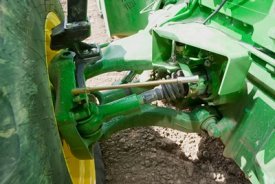
Downforce sensor assemblies are found on row-units with sensor nodes installed. The downforce sensor assembly is assembled with the gauge wheel depth-adjustment handle and provides gauge wheel pressure information to the respective sensor node for data processing.
SeedStar XP full planter performance page
 SeedStar XP planter details
With the capability of monitoring differences in planting performance items such as seed singulation and row-unit downforce, having one screen to view all planter performance elements is needed to understand the whole planting system. SeedStar XP combines all of the various planting performance elements into one full-color, planter overview screen to enable for a quick understanding of relative planting functionality.
SeedStar XP half screens and other features
 SeedStar XP seed singulation half screen
 SeedStar XP seed spacing half screen
Other SeedStar XP monitoring features include:
- Capable of monitoring individual row-unit and overall planter performance in terms of seed spacing, singulation, and row-unit downforce
- Split-screen applications to enable use of popular guidance features such as AutoTrac assisted steering system
- On-screen indication of sensor node/downforce sensor assemblies once configured within the monitor settings application
- Full-color display icons for easy recognition and overall aesthetics
- Pneumatic downforce system controls with the GreenStar display application
SeedStar 2 monitoring original features
SeedStar XP retains all of those SeedStar 2 features that producers value and have come to expect:
-
Planter-at-a-glance – allows operator to view relative population levels of all rows on one screen.
-
Automatic valve calibration – with the SeedStar variable-rate drive (VRD), this is completed automatically. There is no longer a need to manually calibrate the hydraulic valves.
-
Increased population updates – SeedStar will update population levels once per second at planter start up then approximately once every three seconds.
-
Mapping of actual seed rates – when combined with documentation, actual and target seeding rates can be mapped in John Deere Operations Center.
-
Reprogrammable utilizing controller area network (CAN) via Service ADVISOR™ diagnostics system.
-
Improved diagnostics/event recorder – on SeedStar VRD planters, additional diagnostic information is available, as well as an event recorder to capture system performance data at a specific point in time.
-
Ability to run motors at different population levels – on SeedStar VRD, operators running multiple motor systems can run each motor at a different speed, allowing different population levels within a planter.
-
User-configurable high fertilizer pressure alarm – allows the operator to be warned when fertilizer pressure reaches a specific level.
-
Automatic quick-start for SeedStar VRD – no longer does the operator need to press the quick-start button on end row turns to resume planting.
-
Automatic tractor speed source selection – when equipped with an 8000/9000 Series Tractor, the system selects the radar speed or allows for manual speed input selection.
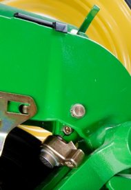 Downforce sensor installed
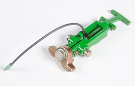 Downforce sensor assembly
Depending on the planter size, different configurations of sensor nodes and downforce sensors are installed in support of the SeedStar XP monitoring system.
Central Commodity System (CCS™)
 1720 CCS with 3523.9 L (100 bu) of seed capacity
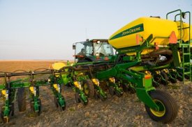
Central Commodity System (CCS) seed delivery adds productivity through increased seed capacity, bulk-fill capability, and easy, thorough cleanout. The two tanks have a combined capacity of 3523.9 L (100 bu) on the 1720 CCS Planters.
The 1720 CCS Planters have been designed to allow for a convenient central filling location and easy cleanout. The rear entry ladder provides access to the filling platform between the tanks.
For those who work into the night, a fill light package is standard on machines equipped with CCS.
If the seed-carrying vehicle requires hydraulic power to run the unloading system, the auxiliary hydraulic coupler option can be ordered. These couplers are located at the bottom of the staircase and can be coupled under pressure. The system has a separate system filter that ensures the planter's hydraulic system remains free of contaminates.
The following crops can be planted with CCS: corn, sweet corn, popcorn, cotton, sunflowers, soybeans, and sorghum (milo).
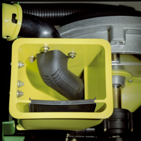
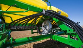 1720 CCS fan and seed delivery hoses
CCS is about reducing the time spent filling the planter with seed while maximizing the time spent planting. CCS for planters is a form of seed handling and delivery. The row-units perform the final task of seed metering and placement.
The CCS seed delivery process relies on a hydraulically driven fan to move seed from the CCS tanks to the row-units. A flow control valve and gauge, located near the tank, allows for the proper tank pressure setting based on seed type.
Air from the fan pressurizes the CCS tanks and delivers seed to the seed hoppers. Air flow enters the seed tanks through a nozzle in the manifold which pressurizes the tank. The air then picks up seed and moves out the other end of the nozzle into the seed delivery hoses. These hoses route the seed toward the hopper. A small amount of seed is traveling in the delivery hoses only when needed.
The hopper fills with seed until the delivery hose (discharge elbow) is covered. Once the opening is restricted, seed flow through the hose stops. Air flowing to the row-unit travels into the hopper and out through a vent. As the seed is picked up by the meter and planted, the seed pool shrinks until the end of the delivery hose is uncovered. At that time, the air flow and seed delivery resume, and the seed pool in the hopper is replenished.
Small-seed CCS components
 Manifold nozzle and nozzle with cover installed
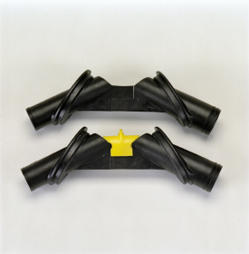
 Small-seed elbow installed in mini-hopper
CCS seed delivery system increases planting productivity across the seven approved crops listed above. While highly effective when delivering seed from the CCS tanks to the vacuum meters, small or light seeds (sorghum and small cotton) will require two additional components to aid in proper seed delivery.
Manifold nozzle covers (clips) should be installed to ensure seed is adequately picked up into the air stream for delivery to the row-unit. Mini-hopper discharge elbows should also be changed from the standard elbow (holes) to the small seed elbow (slotted openings) when planting sorghum (milo) and small cotton.
CCS seed cleanout
Seed cleanout could not be easier with a CCS planter. Whether there are 12 or 48 rows, the CCS system and Pro-Series XP™ row-units make quick work of this chore. When the operator is finished planting, any remaining seed can simply be removed via access doors at the bottom of the CCS tank.
Because seed is only traveling through the CCS delivery hoses when required by the meter, there is not much left to clean.
Next, CCS seed delivery hoses are purged with air from the CCS fan, and the excess seed is pushed to the individual meters.
Lastly, the vacuum meter door is opened, and seed is removed with the supplied catch pan.
Seed variable-rate drive
 Variable-rate drive system
The seed variable-rate drive provides the ultimate planting productivity by utilizing three hydraulic motors to turn the seeding drive shaft. Hydraulic control of the seeding drive allows for on-the-go seeding rate changes right from the display mounted inside the tractor cab. Combine this seeding flexibility with the map-based planting option and seeding rates adjust automatically based on a prescription map.
Seed variable-rate drive requires the SeedStar™ monitoring system and a speed input signal. Either tractor or planter radar may be used or a global positioning system (GPS) speed signal. Radar speed input signal is recommended. Planter radar is ordered separately.
Seed variable-rate drive offers the following advantages:
-
Rate changes are almost instantaneous – no ramp up or ramp down of the system as in some competitive systems
- Permits the operator to match seed population based on different soil types or irrigation practices
- John Deere design provides added operator safety by eliminating any possible drive creep found in some competitive variable-rate drive systems
Three-width drive disconnect
 Three-width drive disconnect control
Three-width drive disconnect feature is activated by three individual console mounted switches (control box) conveniently located in the tractor cab. The function easily shuts off the planter row-unit seed meters by one-, two- or three-drive segments independently.
Lift-assist wheel steering
Hydraulic steering for chassis lift system
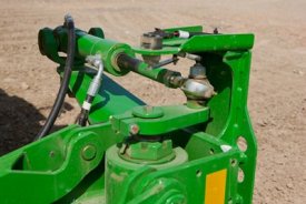 Hydraulic steering cylinder
 Position sensor
The hydraulic steering assists the operator while backing into the next pass. The implement wheels are steered in the opposite direction of the tractor steering wheels when in reverse. The system is calibrated to steer the lift-assist wheels to the ideal steering angle when turning in reverse and guides the planter from a position sensor mounted to the tractor's front axle.
This steering system prevents the lift-assist wheels from casting or spinning around when the direction is changed from forward to reserve. This saves disruption to beds or soil. The hydraulic steering also provides resistance to lift-assist wheels, eliminating vibrations from the wheels while traveling forward, and is most beneficial during transport.
Less hydraulic steering for chassis lift system
 Less hydraulic steering
Less lift-assist wheel steering is available to producers who do not need to guide the lift-assist wheels in reverse. This eliminates the need for the position sensor mounted the tractor’s front axle. The less hydraulic steering option does not provide resistance to vibrations from the lift-assist wheels during transport and allows the wheels to caster or spin around during direction changes.
John Deere Connected Support™ prevents downtime and efficiently resolves issues with revolutionary technology-based solutions
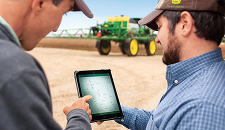 Connected Support technology
When you buy John Deere equipment, you expect reliability. You also know that problems can happen, and a product is only as good as the support behind it. That’s why John Deere equipment is prepared with technology that senses potential issues and can alert you and your dealer promptly—in the cab or anywhere you are.
John Deere Connected Support is a revolutionary change to support that leverages technology and the connectivity of JDLink™ telematics to prevent downtime and resolve problems faster. These tools decrease downtime by an average of 20 percent, enabling faster responses to unexpected problems and reducing technician trips to your machine. For some issues, unplanned downtime can even be prevented altogether through prediction of the issue.
With your permission, John Deere Connected Support:
- Keeps you running by monitoring machine health and promptly alerting you and your dealer of issues
- Saves time by remotely viewing in-cab displays, reducing trips to the machine
- Reduces or even eliminates technician trips to a machine through remote diagnostic and remote software reprogramming capabilities
- Connects experts with the information needed to respond to downtime faster and prevent it altogether
With more than a decade of experience leveraging connectivity to solve problems, no one else has the experience, tools, and knowledge to keep you running as John Deere and your John Deere dealer can. Connected Support is an in-base feature on all John Deere products with factory- or field-installed JDLink.