Buckets
General Purpose (GP) bucketsCompatible with digging teeth and replaceable cutting edgeNot compatible with grapplesThe GP buckets are durable with full length side cutting edges, additional bottom skid plates, and a double reinforced top sectionHoles are drilled in the cutting edge allowing easy attaching of a reversible and replaceable cutting edge
Heavy-duty bucket (shown with grapple)
Materials bucketMaterials buckets may be used for loading dirt, gravel, feed, and light materials as well as scraping, digging, and other general-purpose tasks. NOTE: Materials buckets are not compatible with replaceable cutting edges or digging teeth.
This general-purpose bucket can be used in numerous applications.
The high-volume bucket is intended for use with lighter-density high-volume materials. The bucket capacity makes this an effective tool for handling snow, wood shavings, and other loose materials.
Materials bucketMaterials buckets may be used for loading dirt, gravel, feed, and light materials as well as scraping, digging, and other general-purpose tasks. NOTE: Materials buckets are not compatible with replaceable cutting edges or digging teeth.
Cutting Edges
Replaceable wear edgeFor those who frequently scrape on concrete, a replaceable cutting edge will greatly extend the life of the bucket:1850-mm (73-in.) width replaceable cutting edge2150-mm (85-in.) width replaceable cutting edge2450-mm (96-in.) width replaceable cutting edge2750-mm (108-in.) width replaceable cutting edge
Digging teeth can be added to the heavy-duty bucket for easier digging in hard ground or for breaking loose hard-packed materials such as manure or silage. Digging teeth are not compatible with replaceable cutting edges.
EH Valve
E-ICV Valve and Parts (3rd Function) - BW15987
E-ICV Valve and Parts (3rd Function) - BW15988
Mid-Mount E- ICV Valve and Parts (3rd Function) - BW15314
Front Loader Packages
Stationary fender (H480 shown)Loader stationary fenders are highly recommended for those operating in conditions where the front axle will be in full oscillation and turn frequently or where tight turns are made while maneuvering through gates or obstacles that will catch tractor axle-mounted fenders. The loader stationary fenders still provide coverage for debris from the tire, but they do not protrude to become damaged in operation. The fenders can be removed to enable better access for servicing as well.
Grapples
Five-tine round bale/silage grapple with grilleAll compatible John Deere Loaders use the same five-tine, pin-on grapple. The advantages of this grapple are:The pin-on method puts the least amount of stress possible on the bucket.The grapple has a wide stance, making it more difficult to twist.High-performance operators will choose the five-tine grapple for its increased durability and load-carrying capacity. Advantages include:The ability to handle two large round bales instead of one (where loader capacity allows).Strong grapple arms allow the bucket capacity to be increased by almost twice the amount of normal bucket capacity in materials such as silage.The grapple is equipped with twin cylinders to provide excellent clamping force. NOTE: The center tine of the five-tine grapple is slightly off center to avoid contact with the placement of optional digging teeth.NOTE: The grapple is not compatible with materials or high-volume buckets.1850-mm (73-in.) bale grapple bucket73–in. (1850 mm) grapple bucket BW15358 shown (all one pieceThe bale grapple bucket is a complete solution ideal for full loads of silage, handling bales, or cleaning up debris or manure.
Grapple coupler oil line and bracket - BW16045
Two functionTwo function quick couplerThe H240, H260, H310, H340, and H360 Loaders feature two-function quick-couplers in base machine. To disconnect the hydraulic connection between the loader and the tractor, it is necessary to relieve the hydraulic system oil pressure on the tractor.To watch a video of how to use quick couplers click
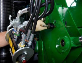
here.NOTE: this video is intended to show the functionality of quick couplers only. Location of the connection varies across different loaders. Three functionThree function quick couplerThe H240, H260, H310, H340, and H360 Loaders can be equipped with three-function quick-couplers. Hoses will be installed in the boom arm and just the couplers will need to be assembled along with the third-function bracket and oil line. To disconnect the hydraulic connection between the loader and the tractor, it is necessary to relieve the hydraulic system oil pressure on the tractor.
Hood Guards
The hood guard's basic function is to:Help protect the tractor grill and hood from falling debris or stationary objects such as a wagon or mixer while loadingAllow for lighting at night Compatibility:Can be used with or without the tractor front weight bracket but not with the actual front weights while using the loader (this would over load the front axle)Cannot be used with a front hitch It is highly recommended to purchase a front weight bracket when using a loader. The hood guard is designed to be slightly rearward of the front weight bracket. This is so that the front weight bracket is the first point of contact against lower stationary objects.
Hood guard for 5E Interim Tier 4 (IT4) 4-Cylinder TractorsThe hood guard's basic function is to:Help protect the tractor grille and hood from falling debris or stationary objects, such as a wagon or mixer, while loadingAllow for lighting at nightCan be used with or without the tractor front weight bracket but not with the actual front weights while using the loaderCannot be used with a front hitchIt is highly recommended to purchase a front weight bracket when using a loader. The hood guard is designed to be slightly rearward of the front weight. This is so that the front weight is the first point of contact against lower stationary objects.
Hood guard for 5M Series TractorsHood guard for 6D Series TractorsThe heavy-duty hood guard is compatible with 5M (5065M, 5075M, 5085M, 5095M, 5100M, 5105M, and 5115M), 6D – model year 2012 and prior (6100D, 6115D, 6130D, and 6140D), 6D – Interim Tier 4 (IT4) model years 2013 -2015 (6105D, 6115D, 6130D, and 6140D), and 6E Final Tier 4 (FT4) model year 2016 (6105E, 6120E, and 6135E) Tractors.The basic function of a hood guard is to:Help protect the tractor grille and hood from falling debris or stationary objects such as a wagon or mixerAllow for lighting at nightThe hood guard:Can be used with or without the tractor front weight bracket but not with the actual front weights while using the loader (this would overload the front axle)For the 5M Series Tractors, the bottom bar must be removed for usage with front hitch for storage position of the center link.It is highly recommended to purchase a front weight bracket when using a loader. The hood guard is designed to be slightly rearward of the front weight bracket. This is so the front weight bracket is the first point of contact against lower stationary objects.If a front weight bracket is not used, the lower bar can be moved downward to improve the protection of the grille below the lights.The features of the hood guard include:Folds down to allow the hood to open and provide access to the battery and filterExtra steel behind the mainframe to increase strengthHigh height to better protect the top of the hood
Hood guard on 6R TractorHood guard for 6R folded downThe hood guard's basic function is to:Help protect the tractor grille and hood from falling debris or stationary objects such as a wagon or mixerAllow for lighting at nightCompatibility:Can be used with or without the tractor front weight bracket but not with the actual front weights while using the loader (this would overload the front axle)Cannot be used with a front hitch It is highly recommended to purchase a front weight bracket when using a loader. The hood guard is designed to be slightly rearward of the front weight bracket. This is so the front weight bracket is the first point of contact against lower stationary objects. The height of the hood guard allows better protection for the top of the hood and allows operators to see the top of the hood guard.
Hoses And Parts
3-Function SLC, M-ICV, Hoses and Parts - BWA1585
Hoses and parts (3-function) - BW15845
Hydraulic Connections
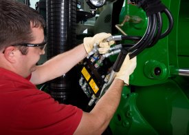
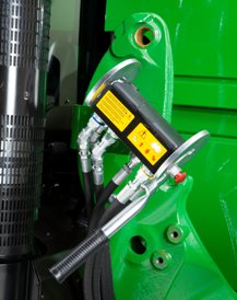
Single-point hydraulic connection on row crop tractorSingle-point hydraulic connection on 5E Series TractorSingle-point hydraulic connection on 5M Series TractorSingle-point hydraulic connection with rigid lines on FT4 6R large frameThe H240, H260, H310, H340, and H360 Loaders feature a single-point hydraulic connection that also incorporates the connection point for any electrical needs as well. To disconnect the hydraulic connection between the loader and the tractor, it is necessary to relieve the hydraulic system oil pressure on the tractor.To view a video of removing the single point hydraulic connection, click
here.
Kit, 3rd Function Quick Coupler Parts - BW16133
Hydraulic Controls
LOADER SUSPENSION SYSTEM
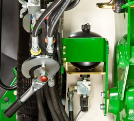
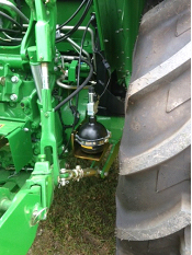
Nitrogen-charged accumulator and electric valveOperator on/off switchLSS on H180LSS on 5E and 5MAn enhancement to the loader is the suspension system. A great level of loader productivity is achieved with the LSS.An accumulator charged with nitrogen and connected to the head-end lift cylinder hose through a T-fitting provides shock absorptionThe cylinders move in and out to allow the boom to float PerformanceBales can be transported more efficiently from one end of the field to the other over frozen, hard-packed, or rutted terrain.NOTE: Check bale-handling capability of tractor before use.Pallets can be moved easily without sustaining cargo damagePallets of seed or fertilizer can be carried across a yard without a bag spilling and creating a costly messA properly-ballasted tractor with LSS has increased stability, creating a smoother ride for the operatorCost of ownershipExtended life of loader pins and bushingsLess stress on tractor axleReasons for turning LSS off include:Digging applications - with LSS on, the cylinders retract slightly, losing lifting powerHolding a grade when blading - with LSS on, it is difficult to hold a constant gradePrecise pallet and bale handling - with LSS on, the load moves up and down slightly while being positionedParking a loader - with LSS on, when down pressure is applied, the lift cylinders retract slightly, making it more difficult to parkThe switch is conveniently located in the operator station to avoid having to exit the tractor seat to manually move the handle on the LSS.LSS can also be ordered with a manual shutoff. Depending on the tractor/loader model, the accumulator is located in different places. On the 440R, the accumulator is mounted outside the bottom of the mounting frame. On the 5 Series Tractors, the accumulator is mounted near the inside of the rear right wheel. On 6 Series tractors and larger, it is mounted in between the hydraulic connection and the mounting frame.
Loader Mounted Fenders
Stationary fender (H480 shown)Loader stationary fenders are highly recommended for those operating in conditions where the front axle will be in full oscillation and turn frequently or where tight turns are made while maneuvering through gates or obstacles that will catch tractor axle-mounted fenders. The loader stationary fenders still provide coverage for debris from the tire, but they do not protrude to become damaged in operation. The fenders can be removed to enable better access for servicing as well.
Loader Suspension System
Nitrogen-charged accumulator and electric valveOperator on/off switchLSS on H180LSS on 5E and 5MAn enhancement to the loader is the suspension system. A great level of loader productivity is achieved with the LSS.An accumulator charged with nitrogen and connected to the head-end lift cylinder hose through a T-fitting provides shock absorptionThe cylinders move in and out to allow the boom to float PerformanceBales can be transported more efficiently from one end of the field to the other over frozen, hard-packed, or rutted terrain.NOTE: Check bale-handling capability of tractor before use.Pallets can be moved easily without sustaining cargo damagePallets of seed or fertilizer can be carried across a yard without a bag spilling and creating a costly messA properly-ballasted tractor with LSS has increased stability, creating a smoother ride for the operatorCost of ownershipExtended life of loader pins and bushingsLess stress on tractor axleReasons for turning LSS off include:Digging applications - with LSS on, the cylinders retract slightly, losing lifting powerHolding a grade when blading - with LSS on, it is difficult to hold a constant gradePrecise pallet and bale handling - with LSS on, the load moves up and down slightly while being positionedParking a loader - with LSS on, when down pressure is applied, the lift cylinders retract slightly, making it more difficult to parkThe switch is conveniently located in the operator station to avoid having to exit the tractor seat to manually move the handle on the LSS.LSS can also be ordered with a manual shutoff. Depending on the tractor/loader model, the accumulator is located in different places. On the 440R, the accumulator is mounted outside the bottom of the mounting frame. On the 5 Series Tractors, the accumulator is mounted near the inside of the rear right wheel. On 6 Series tractors and larger, it is mounted in between the hydraulic connection and the mounting frame.
Nitrogen-charged accumulator and electric valveOperator on/off switchLSS on H180LSS on 5E and 5MAn enhancement to the loader is the suspension system. A great level of loader productivity is achieved with the LSS.An accumulator charged with nitrogen and connected to the head-end lift cylinder hose through a T-fitting provides shock absorptionThe cylinders move in and out to allow the boom to float PerformanceBales can be transported more efficiently from one end of the field to the other over frozen, hard-packed, or rutted terrain.NOTE: Check bale-handling capability of tractor before use.Pallets can be moved easily without sustaining cargo damagePallets of seed or fertilizer can be carried across a yard without a bag spilling and creating a costly messA properly-ballasted tractor with LSS has increased stability, creating a smoother ride for the operatorCost of ownershipExtended life of loader pins and bushingsLess stress on tractor axleReasons for turning LSS off include:Digging applications - with LSS on, the cylinders retract slightly, losing lifting powerHolding a grade when blading - with LSS on, it is difficult to hold a constant gradePrecise pallet and bale handling - with LSS on, the load moves up and down slightly while being positionedParking a loader - with LSS on, when down pressure is applied, the lift cylinders retract slightly, making it more difficult to parkThe switch is conveniently located in the operator station to avoid having to exit the tractor seat to manually move the handle on the LSS.LSS can also be ordered with a manual shutoff. Depending on the tractor/loader model, the accumulator is located in different places. On the 440R, the accumulator is mounted outside the bottom of the mounting frame. On the 5 Series Tractors, the accumulator is mounted near the inside of the rear right wheel. On 6 Series tractors and larger, it is mounted in between the hydraulic connection and the mounting frame.
Nitrogen-charged accumulator and electric valveOperator on/off switchLSS on H180LSS on 5E and 5MAn enhancement to the loader is the suspension system. A great level of loader productivity is achieved with the LSS.An accumulator charged with nitrogen and connected to the head-end lift cylinder hose through a T-fitting provides shock absorptionThe cylinders move in and out to allow the boom to float PerformanceBales can be transported more efficiently from one end of the field to the other over frozen, hard-packed, or rutted terrain.NOTE: Check bale-handling capability of tractor before use.Pallets can be moved easily without sustaining cargo damagePallets of seed or fertilizer can be carried across a yard without a bag spilling and creating a costly messA properly-ballasted tractor with LSS has increased stability, creating a smoother ride for the operatorCost of ownershipExtended life of loader pins and bushingsLess stress on tractor axleReasons for turning LSS off include:Digging applications - with LSS on, the cylinders retract slightly, losing lifting powerHolding a grade when blading - with LSS on, it is difficult to hold a constant gradePrecise pallet and bale handling - with LSS on, the load moves up and down slightly while being positionedParking a loader - with LSS on, when down pressure is applied, the lift cylinders retract slightly, making it more difficult to parkThe switch is conveniently located in the operator station to avoid having to exit the tractor seat to manually move the handle on the LSS.LSS can also be ordered with a manual shutoff. Depending on the tractor/loader model, the accumulator is located in different places. On the 440R, the accumulator is mounted outside the bottom of the mounting frame. On the 5 Series Tractors, the accumulator is mounted near the inside of the rear right wheel. On 6 Series tractors and larger, it is mounted in between the hydraulic connection and the mounting frame.
Nitrogen-charged accumulator and electric valveOperator on/off switchLSS on H180LSS on 5E and 5MAn enhancement to the loader is the suspension system. A great level of loader productivity is achieved with the LSS.An accumulator charged with nitrogen and connected to the head-end lift cylinder hose through a T-fitting provides shock absorptionThe cylinders move in and out to allow the boom to float PerformanceBales can be transported more efficiently from one end of the field to the other over frozen, hard-packed, or rutted terrain.NOTE: Check bale-handling capability of tractor before use.Pallets can be moved easily without sustaining cargo damagePallets of seed or fertilizer can be carried across a yard without a bag spilling and creating a costly messA properly-ballasted tractor with LSS has increased stability, creating a smoother ride for the operatorCost of ownershipExtended life of loader pins and bushingsLess stress on tractor axleReasons for turning LSS off include:Digging applications - with LSS on, the cylinders retract slightly, losing lifting powerHolding a grade when blading - with LSS on, it is difficult to hold a constant gradePrecise pallet and bale handling - with LSS on, the load moves up and down slightly while being positionedParking a loader - with LSS on, when down pressure is applied, the lift cylinders retract slightly, making it more difficult to parkThe switch is conveniently located in the operator station to avoid having to exit the tractor seat to manually move the handle on the LSS.LSS can also be ordered with a manual shutoff. Depending on the tractor/loader model, the accumulator is located in different places. On the 440R, the accumulator is mounted outside the bottom of the mounting frame. On the 5 Series Tractors, the accumulator is mounted near the inside of the rear right wheel. On 6 Series tractors and larger, it is mounted in between the hydraulic connection and the mounting frame.
Nitrogen-charged accumulator and electric valveOperator on/off switchLSS on H180LSS on 5E and 5MAn enhancement to the loader is the suspension system. A great level of loader productivity is achieved with the LSS.An accumulator charged with nitrogen and connected to the head-end lift cylinder hose through a T-fitting provides shock absorptionThe cylinders move in and out to allow the boom to float PerformanceBales can be transported more efficiently from one end of the field to the other over frozen, hard-packed, or rutted terrain.NOTE: Check bale-handling capability of tractor before use.Pallets can be moved easily without sustaining cargo damagePallets of seed or fertilizer can be carried across a yard without a bag spilling and creating a costly messA properly-ballasted tractor with LSS has increased stability, creating a smoother ride for the operatorCost of ownershipExtended life of loader pins and bushingsLess stress on tractor axleReasons for turning LSS off include:Digging applications - with LSS on, the cylinders retract slightly, losing lifting powerHolding a grade when blading - with LSS on, it is difficult to hold a constant gradePrecise pallet and bale handling - with LSS on, the load moves up and down slightly while being positionedParking a loader - with LSS on, when down pressure is applied, the lift cylinders retract slightly, making it more difficult to parkThe switch is conveniently located in the operator station to avoid having to exit the tractor seat to manually move the handle on the LSS.LSS can also be ordered with a manual shutoff. Depending on the tractor/loader model, the accumulator is located in different places. On the 440R, the accumulator is mounted outside the bottom of the mounting frame. On the 5 Series Tractors, the accumulator is mounted near the inside of the rear right wheel. On 6 Series tractors and larger, it is mounted in between the hydraulic connection and the mounting frame.
Miscellaneous
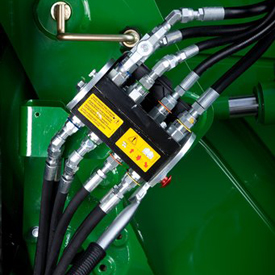
The loader hoses are connected to the mid-tractor selective control valves (SCVs).
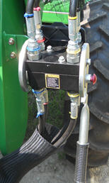
Two functionTwo function quick couplerThe H240, H260, H310, H340, and H360 Loaders feature two-function quick-couplers in base machine. To disconnect the hydraulic connection between the loader and the tractor, it is necessary to relieve the hydraulic system oil pressure on the tractor.To watch a video of how to use quick couplers click
here.NOTE: this video is intended to show the functionality of quick couplers only. Location of the connection varies across different loaders. Three functionThree function quick couplerThe H240, H260, H310, H340, and H360 Loaders can be equipped with three-function quick-couplers. Hoses will be installed in the boom arm and just the couplers will need to be assembled along with the third-function bracket and oil line. To disconnect the hydraulic connection between the loader and the tractor, it is necessary to relieve the hydraulic system oil pressure on the tractor.
2-Function SLC, M-ICV, Hoses and Parts - BWA1510
The loader hoses are connected to the mid-tractor selective control valves (SCVs).
The loader hoses are connected to the mid-tractor selective control valves (SCVs).
2-Function Single Lever Control, M-ICV, Hoses and Parts for Field Installation - BWA1575
Single-point hydraulic connection on row crop tractorSingle-point hydraulic connection on 5E Series TractorSingle-point hydraulic connection on 5M Series TractorSingle-point hydraulic connection with rigid lines on FT4 6R large frameThe H240, H260, H310, H340, and H360 Loaders feature a single-point hydraulic connection that also incorporates the connection point for any electrical needs as well. To disconnect the hydraulic connection between the loader and the tractor, it is necessary to relieve the hydraulic system oil pressure on the tractor.To view a video of removing the single point hydraulic connection, click
here.
The loader hoses are connected to the mid-tractor selective control valves (SCVs).
The loader hoses are connected to the mid-tractor selective control valves (SCVs).
Single-point hydraulic connection on row crop tractorSingle-point hydraulic connection on 5E Series TractorSingle-point hydraulic connection on 5M Series TractorSingle-point hydraulic connection with rigid lines on FT4 6R large frameThe H240, H260, H310, H340, and H360 Loaders feature a single-point hydraulic connection that also incorporates the connection point for any electrical needs as well. To disconnect the hydraulic connection between the loader and the tractor, it is necessary to relieve the hydraulic system oil pressure on the tractor.To view a video of removing the single point hydraulic connection, click
here.
Replaceable wear edgeFor those who frequently scrape on concrete, a replaceable cutting edge will greatly extend the life of the bucket:1850-mm (73-in.) width replaceable cutting edge2150-mm (85-in.) width replaceable cutting edge2450-mm (96-in.) width replaceable cutting edge2750-mm (108-in.) width replaceable cutting edge
The loader hoses are connected to the mid-tractor selective control valves (SCVs).
3 Function Single Point Hydraulic Connection (tractor and loader half) - BW16960
The loader hoses are connected to the mid-tractor selective control valves (SCVs).
3-Function Hydraulic Hoses and Parts - BWA1590
3-Function Hydraulic Hoses and Parts - BWA1591
3-Function Hydraulic Hoses and Parts - BWA1614
3-Function Hydraulic Hoses and Parts - BWA1615
Two functionTwo function quick couplerThe H240, H260, H310, H340, and H360 Loaders feature two-function quick-couplers in base machine. To disconnect the hydraulic connection between the loader and the tractor, it is necessary to relieve the hydraulic system oil pressure on the tractor.To watch a video of how to use quick couplers click
here.NOTE: this video is intended to show the functionality of quick couplers only. Location of the connection varies across different loaders. Three functionThree function quick couplerThe H240, H260, H310, H340, and H360 Loaders can be equipped with three-function quick-couplers. Hoses will be installed in the boom arm and just the couplers will need to be assembled along with the third-function bracket and oil line. To disconnect the hydraulic connection between the loader and the tractor, it is necessary to relieve the hydraulic system oil pressure on the tractor.
3-Function Quick Couplers - BW16958
The loader hoses are connected to the mid-tractor selective control valves (SCVs).
The loader hoses are connected to the mid-tractor selective control valves (SCVs).
The loader hoses are connected to the mid-tractor selective control valves (SCVs).
3-Function Single Lever Control, M-ICV, Hoses and Parts for Field Installation - BWA1576
Single-point hydraulic connection on row crop tractorSingle-point hydraulic connection on 5E Series TractorSingle-point hydraulic connection on 5M Series TractorSingle-point hydraulic connection with rigid lines on FT4 6R large frameThe H240, H260, H310, H340, and H360 Loaders feature a single-point hydraulic connection that also incorporates the connection point for any electrical needs as well. To disconnect the hydraulic connection between the loader and the tractor, it is necessary to relieve the hydraulic system oil pressure on the tractor.To view a video of removing the single point hydraulic connection, click
here.
3-function multi-coupler - BW16402
3-function multi-coupler, loader half - BW16401
Hood guard on 6R TractorHood guard for 6R folded down The hood guard's basic function is to:Help protect the tractor grille and hood from falling debris or stationary objects such as a wagon or mixerAllow for lighting at night Compatibility:Can be used with or without the tractor front weight bracket but not with the actual front weights while using the loader (this would overload the front axle)Cannot be used with a front hitch It is highly recommended to purchase a front weight bracket when using a loader. The hood guard is designed to be slightly rearward of the front weight bracket. This is so the front weight bracket is the first point of contact against lower stationary objects. The height of the hood guard allows better protection for the top of the hood and allows operators to see the top of the hood guard.
Hood guard for 5M Series TractorsHood guard for 6D Series TractorsThe heavy-duty hood guard is compatible with 5M (5065M, 5075M, 5085M, 5095M, 5100M, 5105M, and 5115M), 6D – model year 2012 and prior (6100D, 6115D, 6130D, and 6140D), 6D – Interim Tier 4 (IT4) model years 2013 -2015 (6105D, 6115D, 6130D, and 6140D), and 6E Final Tier 4 (FT4) model year 2016 (6105E, 6120E, and 6135E) Tractors.The basic function of a hood guard is to:Help protect the tractor grille and hood from falling debris or stationary objects such as a wagon or mixerAllow for lighting at nightThe hood guard:Can be used with or without the tractor front weight bracket but not with the actual front weights while using the loader (this would overload the front axle)For the 5M Series Tractors, the bottom bar must be removed for usage with front hitch for storage position of the center link.It is highly recommended to purchase a front weight bracket when using a loader. The hood guard is designed to be slightly rearward of the front weight bracket. This is so the front weight bracket is the first point of contact against lower stationary objects.If a front weight bracket is not used, the lower bar can be moved downward to improve the protection of the grille below the lights.The features of the hood guard include:Folds down to allow the hood to open and provide access to the battery and filterExtra steel behind the mainframe to increase strengthHigh height to better protect the top of the hood
The loader hoses are connected to the mid-tractor selective control valves (SCVs).
2-function hoses and couplers
Hoses and parts (2-function) - BW15844
The loader hoses are connected to the mid-tractor selective control valves (SCVs).
Hoses and parts (3-function) - BW16069
Hoses and parts (3-function) - BW16103
Hoses and parts (3-function) - BW16187
Kit, 3-function single-point connection parts - BW16132
Large ballast box is available to carry additional ballast for greater tractor stability. CapacitiesWeightSand (Dry)ConcretePortland CementBW15852 Large ballast box:Volume13.3 ft3 = 377LMaterial581 kg (1277 lb)871 kg (1915 lb)1089 kg (2395 lb)Empty box155 kg (342 lb)155 kg (342 lb)155 kg (342 lb)Total736 kg (1619 lb)1026 kg (2257 lb)1244 kg (2737 lb)BW15852 Large ballast box is compatible with Category 2 Quik-Couplers and Category 2 or 3 hitches.See ''Rear Ballast Requirements'' for proper ballasting of the tractor.
Mid-mounted independent control valve (2-function) - BW15985
Mid-mounted independent control valve (3-function) - BW15986
5M mounting frame5M mounting frame6E Final Tier 4 (FT4) and 6D Interim Tier 4 (IT4) (model year 2013-2015) mounting frame6D (model year 2012 and prior) mounting frame6M (small chassis), 6R (small chassis), 6030, 6030 Premium, 6020, 6010, and 6000 Series Tractors mounting frame5E 4 Cylinder (IT4; 5085E, 5100E) mounting frameMounting frames are designed to evenly distribute forces during loader operation. Hardware is accessible to torque to the correct specifications.
5M mounting frame5M mounting frame6E Final Tier 4 (FT4) and 6D Interim Tier 4 (IT4) (model year 2013-2015) mounting frame6D (model year 2012 and prior) mounting frame6M (small chassis), 6R (small chassis), 6030, 6030 Premium, 6020, 6010, and 6000 Series Tractors mounting frame5E 4 Cylinder (IT4; 5085E, 5100E) mounting frameMounting frames are designed to evenly distribute forces during loader operation. Hardware is accessible to torque to the correct specifications.
5M mounting frame5M mounting frame6E Final Tier 4 (FT4) and 6D Interim Tier 4 (IT4) (model year 2013-2015) mounting frame6D (model year 2012 and prior) mounting frame6M (small chassis), 6R (small chassis), 6030, 6030 Premium, 6020, 6010, and 6000 Series Tractors mounting frame5E 4 Cylinder (IT4; 5085E, 5100E) mounting frameMounting frames are designed to evenly distribute forces during loader operation. Hardware is accessible to torque to the correct specifications.
Mounting frame - BW16087
Power Beyond spacer - BW15989
Single-level control and valve (2-function) - BW15773
Single-level control and valve (3-function) - BW15774
Single-lever control and mounting parts 3-function with Global Strategic Supplier (GSS) - BW15785
Single-lever control and mounting parts 3-function with Global Strategic Supplier (GSS) - BW15807
Tool box bracket - BW16126
Tool box bracket - BW15971
Miscellaneous
Mounting Frames
5M mounting frame5M mounting frame6E Final Tier 4 (FT4) and 6D Interim Tier 4 (IT4) (model year 2013-2015) mounting frame6D (model year 2012 and prior) mounting frame6M (small chassis), 6R (small chassis), 6030, 6030 Premium, 6020, 6010, and 6000 Series Tractors mounting frame5E 4 Cylinder (IT4; 5085E, 5100E) mounting frameMounting frames are designed to evenly distribute forces during loader operation. Hardware is accessible to torque to the correct specifications.
Mounting frame - BW16095
Mounting frame - BW15885
OPERATOR'S MANUAL AND DECAL KIT
French North American operator's manual and decal kit - BW16142
Spanish North American operator's manual and decal kit - BW16143


 Single-point hydraulic connection on row-crop tractor (closed)
 Single-point hydraulic connection on utility tractor (closed)
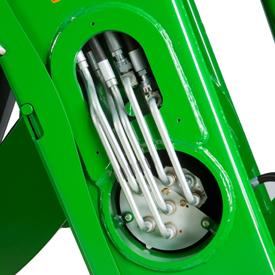
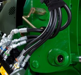
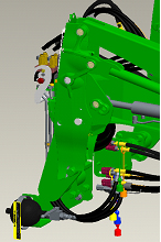
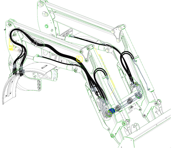 Concealed oil lines through boom arm
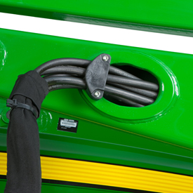 Oil lines routed through the boom arm
 Oil lines routed through the torque tube
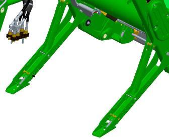 Parking stands
 Parking stand in stored position
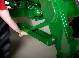 Removing parking stand
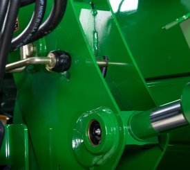 Mast pin in the closed position
 Rotating mast pin to the open position
 Mast pin in the open position
 Masts rotate forward, then bucket rolled back
 Disconnect/open single-point hydraulic connection
 Disconnect/open single-point hydraulic connections
 Single-point hydraulics disconnected
 Parked loader
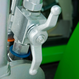 Hydraulic shut-off valve (open position)
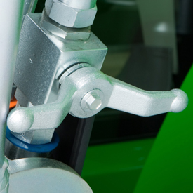 Hydraulic shut-off valve (closed position)
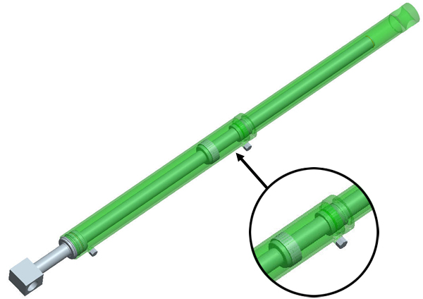 False rod cylinder
 Nitrogen-charged accumulator and electric valve
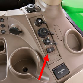 Operator on/off switch
 LSS on H180
 LSS on 5E and 5M